Engineering is a complicated thing, especially when it comes to N14 liner protrusion. We often try to stay away from asking why one manufacturer does something differently than another when, for years, it has worked great the way it was. We would drive ourselves crazy trying to keep up with all the changes and differences in how things get done—especially when they’ve worked for years—as if the engineers just needed something to do that day to justify their paychecks.
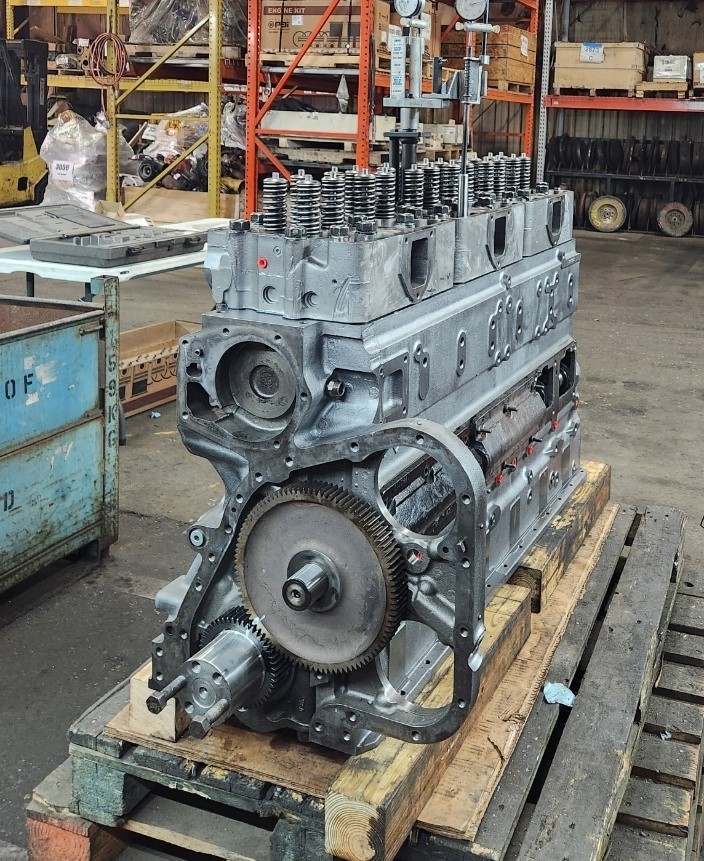
The top of an N14 liner falls into this category. When you look at the top of an N14 liner, you can see there is a fire ring built into it. Obviously, we know why they did this, but with a 525 HP and below engine, it has us wondering if it was necessary—or if it was just an engineer trying to justify his place on this earth.
This brings us to the next question: where do you properly measure the liner when measuring inside of the block with a liner protrusion sled gauge?
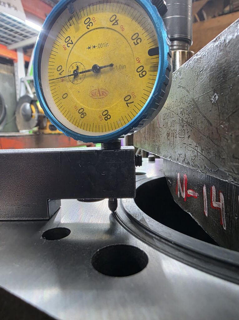
For years now, we’ve always cut our counterbores so that the measurement on the liner—outside of the fire ring—is .007″ because that is “just how we have always done it” (see graphic 1).
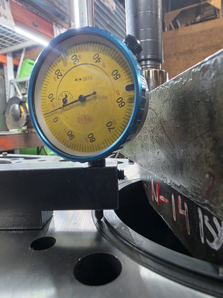
When you measure inside the fire ring, the measurement drops about .003″ and a lot of the time puts you at or just below that minimum spec, which is somewhere you don’t want to be (see graphic 2).
Just recently, we were all out of N14 blocks and had to purchase one from a reputable supplier for a customer who was in a hurry to get their engine. When we measured this block, the measurement outside of the fire ring was .010″, and inside the fire ring it was .007″. We circled back to this supplier, and their response was that it is “just how we have always done it.”
We wanted to know what the OE had to say about this. We then called a couple of OE Cummins dealers and got a wide range of answers—from “you don’t measure on top of the fire ring” to “you don’t measure that upper deck, you measure the lower deck”—as if we were rookie engine builders that didn’t know what we were doing. The manuals we had on hand, along with what we could find on QuickServe, gave us measurements but didn’t clearly state where those measurements were to be taken.
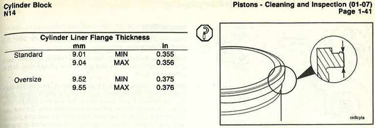
When local dealers gave inconsistent or unhelpful answers, PAI Industries provided the OEM graphic and clarity we needed. After giving up on the local OE Cummins dealers—who obviously didn’t care enough to help or even educate themselves—we went to someone who has always been there to support us: PAI Industries. They were able to get us an OEM graphic showing exactly where to measure the liner thickness spec of .356″ to .366″ (see graphic 3). Finally, after a week of frustrating explanations trying to get our questions answered, we had literature supporting the way we have done it for years. The proper way is to measure outside of the fire ring.
Pro Tips:
- You need to have a dial indicator with a pointed tip in order to get this measurement. A thicker dial indicator will want to ride up on top of the fire ring because there is not a lot of material outside the fire ring to measure.
- OEM liner protrusion spec is .004″ to .007″, and as long as you are within this spec, we would expect the engine to operate properly with no head gasket issues. N14 engines are not known for head gasket issues, and maybe this is something we should thank that bored engineer for when he changed the liner to have the fire ring. Even though we like to keep the measurement at .007″, there is nothing wrong with moving forward with a lower spec as long as it is above .004″.
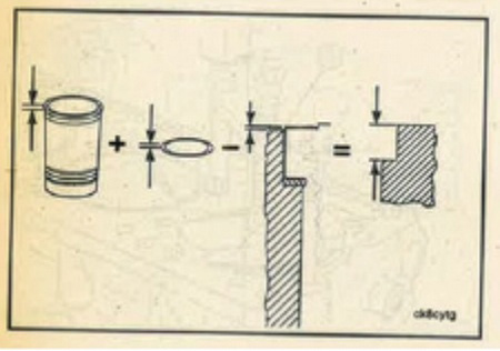
- You can measure your counterbore depth, then add your shim thickness and measure your liner flange all separately to math out each cylinder (as illustrated in graphic 4). This process is argued to be even better, but we prefer to do both. During machining, measuring is the way we do it, but during assembly we like to measure the liner after it is already in the block.
- Don’t forget to use a liner press to hold the liner down while measuring.
HAPPY BUILDING! MAY YOUR LIFE BE FILLED WITH MANY SMOOTH REVOLUTIONS.